Role

Individual — CAD Modeling & FEA Simulation

Structures · ERAU

Tools

Fusion 360 · FEMAP · NX Nastran

Key Contributions

  • Modeled full wing assembly including spars, ribs, stringers, and skin panels in Fusion 360
  • Transferred geometry to FEMAP and solved with NX Nastran under distributed aerodynamic loading
  • Validated mesh quality with Jacobian values above 0.6 across all elements
  • Interpreted stress and displacement contours to confirm structural adequacy and identify load paths
>0.6
Min Jacobian
0.15 in
Peak Tip Displacement
3D
Full Assembly Model
FEA
NX Nastran Solver

This page covers a full structural analysis workflow for an aircraft wing — from 3D CAD assembly in Fusion 360 through finite element analysis in FEMAP and NX Nastran — ending with stress and displacement results that confirm the wing's structural adequacy under flight loading.

Project Overview

Structural analysis of an aircraft wing under aerodynamic loading is one of the most fundamental tasks in aerospace engineering design. This project covered the complete workflow from 3D CAD geometry creation through finite element analysis, with the goal of assessing stress distribution and deflection behavior under realistic flight loads.

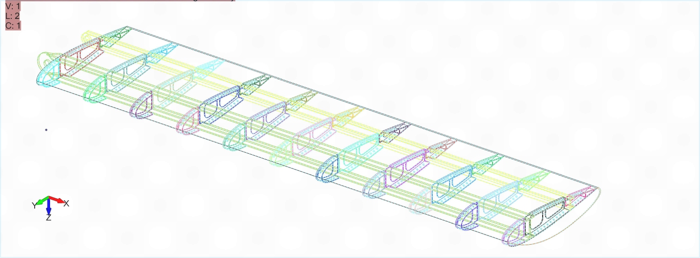
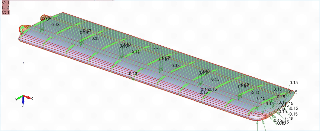
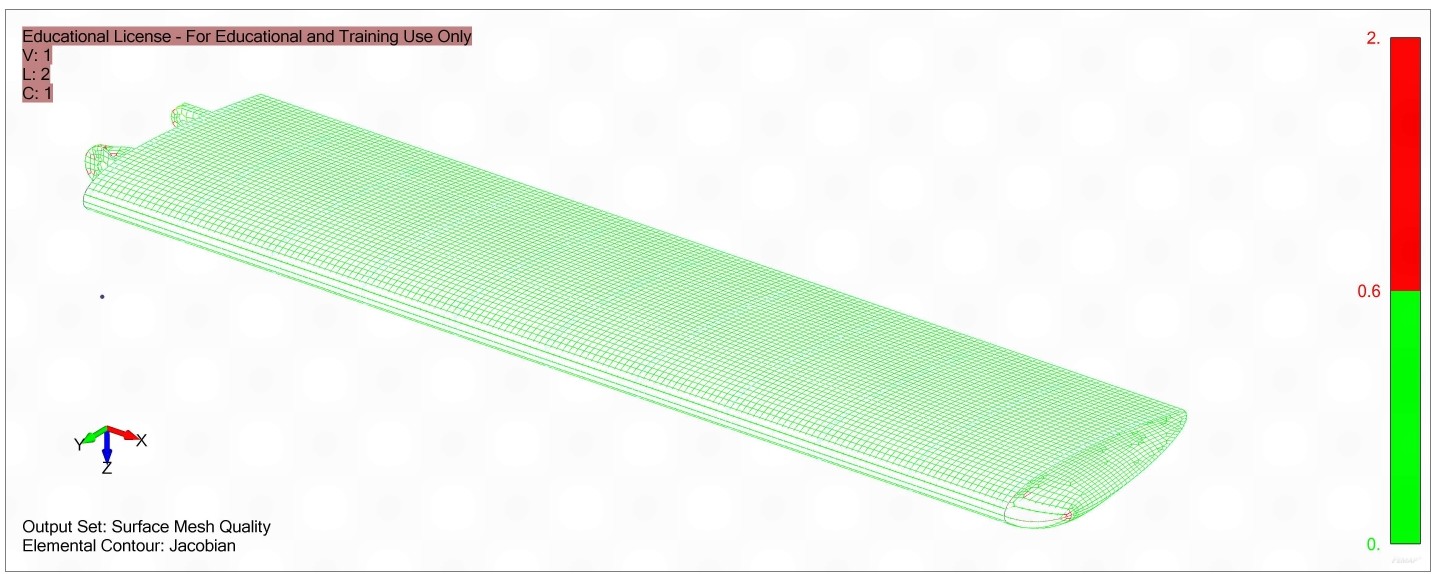
The wing assembly was modeled in Fusion 360 with all primary structural members included, then transferred to FEMAP for preprocessing — where loads and boundary conditions were applied and the mesh was generated and validated — before solving with NX Nastran.

Aircraft wing 3D CAD assembly in Fusion 360
Fig. 1: 3D wing assembly in Fusion 360 — spars, ribs, stringers, and skin panels fully modeled before FEA transfer

CAD Geometry & Assembly

The wing was modeled as a full structural assembly rather than a simplified shell, capturing the load-carrying behavior of each member:

Particular attention was paid to interface geometry between components, ensuring that mating surfaces were flush and that no gaps or overlaps would cause meshing artifacts during FEA preprocessing. The assembly was exported in a format compatible with FEMAP for direct geometry import without manual reconstruction.

Finite Element Analysis

Design Decision

Trade-off: Modeled the skin panels with shell elements and the spars and stringers with beam elements, rather than meshing the entire assembly with solid (3D) elements.

Why: The skin is thin relative to its planar dimensions, and the spar/stringer caps are long, slender members — both are well-represented by 1D/2D idealizations without the element-count explosion a solid mesh would require. This kept the model small enough to refine locally near the spar root, where the stress gradient is steepest, while still resolving the load paths (bending in the spars, shear flow in the skin) that the analysis was meant to capture.

Key results from the NX Nastran solution:

Finite element mesh of the wing assembly in FEMAP
Fig. 2: Finite element mesh in FEMAP — shell elements for skin, beam elements for spars and stringers, Jacobian > 0.6 across all elements
Von Mises stress and displacement contour output from NX Nastran
Fig. 3: NX Nastran output — von Mises stress contour showing peak loading at the front spar root; tip displacement of ~0.15 in under distributed aerodynamic load

Key Takeaways

CAD quality directly controls FEA validity

Interface gaps or overlapping surfaces in the Fusion 360 model cause meshing failures or poor Jacobian values in FEMAP. Cleaning geometry before export eliminated all preprocessing issues and allowed the mesh to be generated without manual repair.

Spars dominate bending load paths

The von Mises contour confirmed that front spar root stresses were significantly higher than skin panel stresses. In a cantilever wing, the spars carry the majority of bending moment and shear, with skin panels primarily carrying torsional shear flow.

Mesh refinement at stress risers improves solution accuracy

Applying local mesh refinement near the spar root and spar cap intersections captured the stress gradient more accurately than a uniform mesh. This prevents artificially smooth contours from obscuring genuine stress concentrations in high-load regions.

Jacobian validation is a necessary pre-solve check

Reviewing Jacobian values before submitting to Nastran caught distorted elements near rib cutouts that would have degraded solution quality. Re-meshing those regions resolved the issue. Relying only on visual mesh inspection is insufficient for production FEA work.

← Back to Aerospace Projects